Laser Marking 301: Laser Marking Techniques
Editor’s Note: This article was first published in Photonics Online. You can read the original...

Marking field size limitations have always been a drawback for steered beam (galvo driven) laser marking systems. Unlike flying optics type systems which move a simple lens over a marking field that is only limited by the size of the X-Y drive system, steered beam laser marking systems use flat field or F theta lenses which allow the laser beam to be focused in a flat plane centered under the lens.
The lens components dictate the size of the marking field plane and the resulting size of the focused laser spot increases proportionally with the size of the marking field. It is important to realize that, since power density in the focused laser spot depends on the area of that focused laser spot, doubling that marking field doubles the spot size but decreases the power density by a factor of four. Very large marking fields are not practical with steered beam fiber laser marking systems. Marking fields larger than about 12 inches square produce focused spot sizes that are too large to provide sufficient power density for engraving applications and linewidths too broad for detailed marking applications. Useful marking fields for steered beam fiber laser marking systems are usually in the 4 X 4 to 9 X 9 inch range.
In order to achieve large marking fields with steered beam fiber laser marking systems, the information to be marked must be sectioned into “tiles” that are no larger than the marking field and some type of motion system must be used to reposition the part to be marked under the lens such that the correct tile is positioned over the correct portion of the part. Usually, some type of motion system is employed that co-ordinates part positioning and tile marking such that the proper tile is marked in the proper location of the part. In the simplest form, the part can be repositioned manually by the operator although a precision motion system will always provide superior results. We refer to the technique of breaking a marking area into individual field sized segments as “tiling”.
So, why would anyone go to the effort of segmenting a large mark into individual tiles in the first place when flying optics type systems already offer large field marking. The answer generally comes down to speed and mark quality. Galvo driven systems are several times faster than flying optics systems. Flying optics type systems must move the mass of the lens and carriage assembly as they traverse the marking field whereas galvo driven systems only need to rotate a shaft with a mirror attached to it. Galvo driven systems are incredibly faster than flying optics systems.
Tiling becomes a relatively simple operation if each tile only contains discreet and complete marking objects, that is, none of the objects to be marked are split between two or more tiles. In this case, the laser marking software and the motion system that moves the part only need to “handshake” with each other and the laser marking software doesn’t need to . As long as the motion system moves the part to the proper location for the tile that is about to be marked, all is well. Once the motion system has the part in position, it can “handshake” with the marking software and the information in that tile is marked in that location.
Things get a lot more complicated when marking objects are large enough that they fall into two or more tiles. Take a look at the photo of the wall mural below. This wall mural is 7 ½ feet long and 2 ½ feet wide and was engraved with a 50 watt fiber laser system that only had a 7.2 inch square marking field.
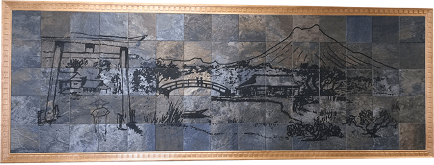
The original image was created as a vector file in an HPGL format. The engraving required a vector file because a bitmap image would not allow the marker to draw the individual lines with enough overlapping laser pulses to achieve the necessary depth into the material. So, the graphic image had to be broken up into individual 6 inch square tiles and when a new section was marked, continuous lines in each tile had to connect. The only limits to laser tiling are the available space under the lens or the amount of travel in the axes of the positioning system.
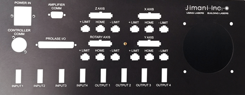
The wall mural wasn’t particularly challenging from a laser tiling standpoint but it was challenging from an overall size standpoint. Because the mural substrate consisted of individual 6 inch squares of material, a natural border existed between tiles and if continuous line segments didn’t exactly match up, the border masked the irregularity. Most laser tiling applications are not done on substrates consisting of small segments, they are done on single parts that exceed the size of the marking field. Nineteen inch wide electronic chassis panels are a common application. The panel below is used on one of the control chassis for our Langolier Fiber Laser Marking Systems. Although each marked element is smaller than the laser marking field, it was far easier to lay out the panel marking as a single graphical element and then let our Prolase Laser Marking software break the image into individual tiles, each tile being smaller than the marking field of the laser marking system. Several of the text objects were on different tiles and, in some cases, individual letters were on different tiles. It this example the tile positioning was critical because unconnected or overlapping line segments would be blatantly obvious.
So, what things can cause disconnected line segment that are supposed to be continuous when performing laser tiling in the X or Y axes? Let’s make the assumption that the software does a good job of breaking up the image into individual tiles.
Part Positioning Accuracy- If the part cannot be positioned accurately for each tile location, whether the positioning is performed manually or with a motorized linear drive, there is 0 chance of continuous lines in adjacent tiles lining up. A single line drawn with a fiber laser on an anodized aluminum substrate will have a linewidth of approximately .0025 inches. If, when positioning from tile to tile, the cumulative positioning error is greater than a laser linewidth, a noticeable seam will exist. That seam could be in the form of a gap or an overlap.
Marking Field Accuracy- If the marking field is calibrated correctly then any object that is marked within that marking field should to the correct size within a laser line width. Proper focus plays a part in this. Marking field calibration should be performed with the focusing lens at its exact focal point. If the part to be marked is not placed at this same focal distance from the lens then the marking field is no longer calibrated. If the lens is too far away from the part then the marks in the field will be larger than they should be and, conversely, if the lens is too close to the part, the marks will be smaller than they should be. A small error in focus position can produce a very noticeable error in lines that should be connected on adjacent tiles.
Alignment between positioning system axes and galvo axes- If the X-Y axes of the part positioning system and the X-Y axes of the galvo system are not exactly parallel, connected lines in adjacent tiles will appear to be offset by a distance determined by marking tile size and angular misalignment between the galvos and the part positioning system axes.
If all of the above conditions are met, linear tiling is a piece of cake. Rotary tiling, however, can be more challenging.
When performing rotary tiling, the axis of rotation of the part must be parallel to the galvo axis. If the rotary axis has any tilt with respect to the galvo axis, marked tiles will never align together without seams. A difference between rotary tiling and linear tiling is that as the laser marks an object around a cylinder, the marking begins to distort. The further the marking is around the circumference of the cylinder, the more distorted the mark becomes. You can visualize this if you imagine a circle being marked around a cylinder. The marked circle becomes oval shaped and grows in size. For this reason, marking large tiles is not practical on cylindrical shaped objects. Although some marking software programs, such as Prolase Plus, have distortion correction schemes, better results will be achieved if marking tiles are held to about 30 degrees or less.
If the rotary device doesn’t have enough resolution or if rotary calculations are based on improper or fluctuating measurements, such as the diameter of the part, seams are going to be present in the marked part. Seams can be in the form of gaps between tiles or discoloration due to overlap in the tiles.
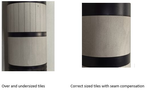
Some amount of seam compensation can be achieved in software as shown in the two photos above but seam compensation is always trying to hide problems created by hardware shortcomings. The rotary device must be capable of moving the cylinder to be marked in an axis of rotation that is perfectly parallel to the galvo axis and the rotation must have sufficient resolution such that adjoining tiles are positioned with less than a laser linewidth of error.
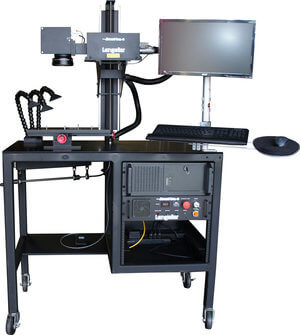
Size limits on rotary tiling only have to do with the ability of the rotary device to accurately locate and hold large parts and the ability of a laser marking workstation to focus on the surface of a large diameter part. Unless you are just marking nameplates, you can never have enough Z axis adjustment for focus.
Large field marking with galvo drive systems can be challenging and cannot be accomplished without good quality hardware and software. Please feel free to contact the author if you have any comments about or suggestions to improve the quality of linear or rotary tiling.

Editor’s Note: This article was first published in Med Device Online. You can read the original article here.