5C Collet Holder For Rotary Laser Marking
A potential customer asked if we could find a way to use 5C collets with the Sherline Rotary Indexer
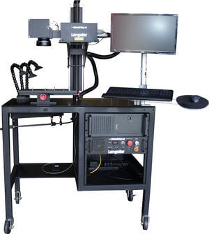
Using the Jimani External Axis Servo Controller and Prolase 7 Plus software, Jimani’s Langolier Fiber Laser Marking Systems are now capable of marking graphics or text completely around the circumference of a cylinder.
Logos, text and graphics can automatically be transformed into “tiles” of a user selectable size using an accurate rotary indexing system that can communicate with Prolase 7 Plus, such as Jimani’s External Axis Servo Controller coupled to a rotary indexer system.
Each tile represents a section of the marking object(s) in the current rotary position and the rotary indexer will automatically rotate the part to the next position, mark the appropriate tile and then continue this sequence until the entire part is marked. Marking a logo, graphic or text object to as much as 360 degrees around the circumference of the part becomes easy to setup, quick to mark and provides a good looking product.
Most 360 degree circumferential marking has been historically accomplished by making the marker act like a dot matrix printer. Dot matrix printers work by printing a row of pixels in the image, advancing the paper by a pixel height and then printing another row of pixels.
This process continues until everything is printed. Some laser markers employ this technique to laser mark bitmap images on round parts. The laser will print a row of pixels in the bitmap image and then the rotary indexer will advance the part by the height of one pixel and the process continues until the entire image is printed. This is a slow process and can only be used with bitmap images.
Steered beam (galvo driven) laser markers act more like plotters than they act like dot matrix printers. For a variety of reasons, speed and quality being two of those, steered beam markers work best when they draw lines, not place pixels. Those lines, whether they are graphics or text, are in a vector image format.
The difficulty has been in separating portions of those lines in a vector image. Imagine a straight line to be marked around the circumference of a cylinder. The line itself is a vector image but it must be broken into parts before it can successfully be drawn around the circumference of a cylinder without distortion or focus issues.
The “Auto-Tiling” feature in Prolase 7 Plus automatically breaks the most complicated vector graphics into segments or tiles. When coupled with an accurate rotary indexer that can communicate with Prolase 7 Plus, the proper tiled segment can be placed in the correct rotary orientation of the part and graphics or text can be marked completely around the circumference.
When coupled with the “Projection Correction” feature in Prolase 7 Plus, the size of the tiled segments is only limited by the depth of focus of the laser on the material that is being marked.
In this video the same logo is marked 4 times on the same cylindrical part. The first mark is made without rotating the part or without distrotion correction, The next mark is made without rotating the part but with Prolase "Projection Correction" enabled. The 3rd and 4th marks are the same logo at larger sizes but using the Prolase "Auto-Tiling" feature.