What is the Best Stainless Steel Marking System
Like so many marking applications there is no single answer to the question of what is the best...
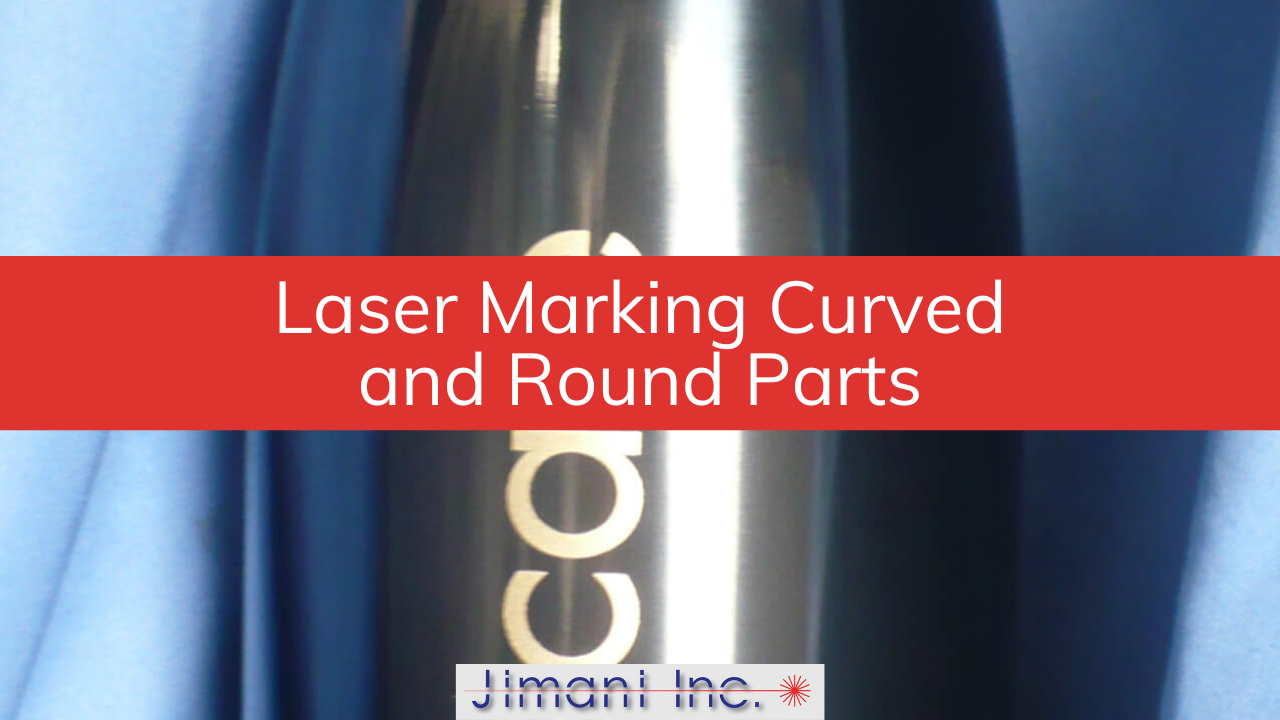
Most laser marking setups are designed around flat parts. The lens is parallel to the surface, the part sits on a flat tooling plate, and everything is exactly at the focal point of the lens. Flat parts are easy. Round parts, small parts, stepped parts, and irregularly shaped parts are where people run into trouble — often because they assume the laser can do more than the physics actually allows.
The good news is that fiber lasers handle a wide range of difficult geometries. The honest news is that each geometry imposes its own set of real constraints. Knowing where those boundaries are — and what to do when you hit them — is what separates a clean production mark from a rejected part.
How Far Around a Cylindrical Part Can a Fiber Laser Mark Without Rotating It?
A fiber laser can mark approximately 60 degrees around the circumference of a 1-inch diameter cylinder without rotating the part — assuming the material matches the laser wavelength well. Beyond that arc, the focused spot begins to drift outside the depth of focus of the lens, power density drops, and mark quality deteriorates at the edges.
This limit is a function of geometry, not laser power. As the beam moves away from the top of the cylinder toward the edges, two things happen simultaneously: the surface curves away from the focal point of the lens, and the angle of incidence between the beam and the surface changes. Some materials are forgiving of small focus shifts — bare aluminum tends to tolerate it reasonably well — while others, particularly coated surfaces where contrast depends on precise ablation depth, will show visible quality degradation long before you've reached 60 degrees.
The 60-degree figure applies to a 1-inch diameter part. Larger diameters give you a bit more angular range before the surface drops outside the depth of focus. Smaller diameters are less forgiving. If your part is half an inch in diameter, expect the usable arc to shrink accordingly.
At Jimani, we've marked hundreds of cylindrical parts in the job shop without rotation — pen barrels, small medical components, shaft sections — and the 60-degree rule holds up consistently as a safe planning number. You can push it somewhat, depending on the material and how tolerant the application is of slight edge softening, but it's a good ceiling to design around before committing to a fixture.
A rotary indexer becomes necessary when the required mark extends beyond approximately 160 degrees of circumference, when geometric distortion in the mark is unacceptable, or when the depth of focus of the lens is exceeded before the desired arc is complete. Any of those three conditions — alone or in combination — means the part needs to rotate.
The 160-degree figure might sound generous compared to the 60-degree rule for clean marking without distortion, and it is. Between 60 and 160 degrees, marking is physically possible if you use software-based projection correction to compensate for the geometric distortion that occurs when the laser draws on a curved surface. Prolase 7 Plus software includes a Projection Correction feature that recalculates the shape of the mark so that characters and logos read correctly on the finished part — a circle marked on a cylinder will otherwise look like an oval. With projection correction active, that same circle reads true. Without it, the mark is visually distorted and may be dimensionally unacceptable depending on the application.
Beyond 160 degrees — or when a mark needs to go all the way around the circumference — the only option is rotary tiling. This works the same way as flat-part tiling for oversized graphics: the mark is divided into sections, the rotary indexer advances the part by the angular width of each tile, and the sections are stitched together. The indexer's positioning accuracy is not a trivial detail here. A single laser line has a kerf width of roughly .002 to .003 inches. The rotary must place successive tiles within that tolerance, or seams will be visible in the finished mark.
At Jimani, we use rotary encoded servo motors on a Sherline rotary indexer with a resolution of 144,000 steps per full 360-degree revolution — enough to hold tile-to-tile registration well within the kerf width.

The right fixturing approach for small or irregularly shaped parts depends on two things: how precisely the mark needs to be located on the part, and how repeatable the fixture needs to be across a production run. For round parts, a 3-jaw self-centering chuck positions the part accurately and releases it quickly. For irregularly shaped parts, custom nests or tooling plates are almost always the right answer.
Small parts present a specific problem that often surprises new users: the part may be positioned correctly, but if it can rock or shift slightly during marking, the focal distance changes mid-mark and the result is inconsistent quality across a single pass. A part that lifts .030 inches off the tooling surface might still look properly seated to an operator, but that height change can put the surface outside the depth of focus of the lens — particularly with smaller field lenses where the depth of focus is tightest.
For very small parts with tight marking areas, the choice of lens matters as much as the fixture. Smaller marking field lenses — say, a 4.7-inch field versus an 8-inch or 12-inch field — focus the laser to a smaller spot, which increases power density and resolution. The tradeoff is that the smaller the field lens, the shallower the depth of focus and the more precisely the part surface needs to be positioned at the focal point. When you're marking a feature that's .060 inches tall with characters requiring tight resolution, a small-field lens with a stable fixture almost always outperforms a large-field lens with a casual setup.
Stepped parts — parts with marking requirements on surfaces at different heights — introduce another layer of complexity. If the height difference between marked surfaces falls within the depth of focus of the lens, nothing has to move and both surfaces can be marked in a single job. If the height difference exceeds the depth of focus, either the Z axis has to be repositioned between marks, or the part has to be re-fixtured. This is a situation where a workstation with motorized Z-axis control earns its cost quickly, particularly in production environments where manual repositioning adds time to every cycle.
Different optics — specifically a beam expander or a different focal length lens — are the right solution when the geometry of the part or the marking requirement cannot be addressed by repositioning the part or rotating it. The most common case is stain marking on curved or radiused parts, where the standard focused spot size is too small and moving the part out of focus to compensate creates inconsistent results across the radius.
Stain marking — the technique used to create a non-penetrating dark oxide layer on stainless steel, titanium, and a few other metals — requires a specific, larger spot size at the focal point of the lens. The straightforward workaround is to move the part slightly out of focus, which spreads the beam. That works fine on flat surfaces. On curved or radiused surfaces, "out of focus" changes continuously as the beam moves around the part. The edge of the mark that's closest to the focal point gets a different spot size than the edge that's further away, and the result is a mark with uneven darkness or contrast that ranges from barely visible to overcooked within a single marking field.
The solution is to change the focused spot size optically, so the correct spot size is delivered at the focal point of the lens rather than away from it. A reversible beam expander placed in the beam path before the focusing lens de-collimates the beam, increasing the focused spot size at the focal point and extending the depth of focus at the same time. This keeps spot size consistent as the beam moves across a radius. It's a more expensive configuration than running without a beam expander, but on stain-marking applications over curved surfaces, it's the difference between a production-quality mark and a guessing game with focus positions. Jimani's Desktop and Enclosed Hybrid systems include a 1.5X reversible beam expander as a standard component for exactly this reason.
A fiber laser marking system becomes the wrong tool for a difficult part when the geometry requires true three-dimensional marking — where the surface contour changes significantly within a single marking field and neither tiling nor Z-axis repositioning can account for it. At that point, the application requires a 3D marking system with a focus-control axis, which is a different category of equipment.
Very deep engraving on narrow features also runs into practical limits that a general-purpose marking system isn't designed to overcome. Engraving beyond .015 to .020 inches of depth is achievable in principle, but the practical problems compound quickly. Vaporized material accumulates on the sidewalls of a narrow engraved trough rather than escaping cleanly, the effective focal point changes as depth increases, and the time required for additional passes grows significantly. For applications requiring .030 inches or more of engraving depth on narrow character lines, a rotary mechanical engraver or a dedicated deep-engraving laser system will do the job more efficiently and with better results.
The honest version of "when to use a different approach" is this: if you're working around the geometry more than you're marking it — stacking workarounds on workarounds to get a marginal result — it's worth a conversation about whether the process is a good match for the part. At Jimani, we run both the job shop and the equipment business, which means we regularly encounter applications that don't fit neatly into a standard setup. Sometimes the answer is a rotary. Sometimes it's different optics. And occasionally, the best service we can offer is telling a customer that a different process would serve them better.
If you're working through a marking application on a difficult part shape, send us the details or ship us a sample. We'll run it in the job shop and tell you exactly what the part requires before you commit to a system or a process.
Related reading: Laser Marking 201: Marking Various Part Shapes | Laser Marking 101: How a Fiber Laser Marking System Works | Laser Marking and Engraving Job Shop Services